
Ask any quality control engineer what keeps them up at night before a pipe or vessel goes out the factory gate, and the answer is usually the same: pressure failure after installation. A weld that looked fine under a visual check, a casting with a hidden void, a flange joint that seemed tight — all of these can surface only once real pressure hits the component. That’s the exact gap this piece of equipment is built to close.
This article looks specifically at the pump itself — what it is, how it generates and holds pressure, the different types available, and the wide range of equipment it’s used to test. If you’ve ever wondered why a small, unassuming device carries so much responsibility on a shop floor, this should answer that.
What Does This Equipment Actually Do?
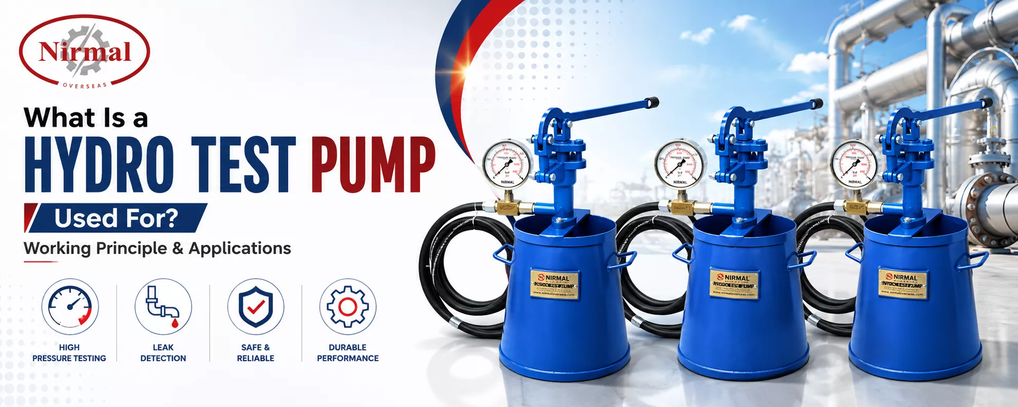
At its simplest, a hydro test pump is a pressurising device used to fill a component with water (or another test fluid) and raise its internal pressure to a set value, so that leaks, weld defects, or structural weaknesses can be identified before the item is put into service. It’s the tool that physically does the pressurising in a hydrostatic test — whether that test is happening on a factory floor, at a construction site, or during a routine maintenance shutdown.
Unlike a full testing line built into a production system, this is typically a standalone unit — compact enough to move between test stations, simple enough for a single technician to operate, and versatile enough to test items that never touch a production line at all, such as installed piping, fire hydrants, or field-repaired vessels.
How Does a Pressure Testing Pump Work?
The core idea is straightforward: mechanical input — hand force, an electric motor, or an air-driven drive — gets converted into hydraulic pressure inside a sealed test piece. The general sequence looks like this:
- Filling the test piece. Water is drawn from a reservoir and fed into the component through the suction line, displacing trapped air as it fills.
- Air venting. Any air pocket left inside the item will compress instead of showing a true pressure reading, so vent valves stay open until a steady stream of water confirms the piece is fully filled.
- Pressurisation stroke. A plunger or piston inside the cylinder moves back and forth, drawing water in on the intake stroke through a suction valve and forcing it out on the delivery stroke through a discharge valve. Each stroke adds a small increment of pressure inside the closed system.
- Check valve action. Non-return valves on the suction and delivery sides stop water from flowing backward between strokes, which is what allows pressure to build cumulatively rather than bleeding off after each cycle.
- Holding the pressure. Once the target pressure is reached, the delivery valve shuts and the system gets isolated. A calibrated gauge tracks the pressure over the hold period — this is the part of the process an inspector actually watches.
- Relief protection. A spring-loaded relief valve, preset slightly above the target test pressure, opens automatically if pressure climbs too high, protecting both the test piece and the operator.
- Depressurising. Once the hold period ends and the result gets recorded, a bleed valve releases pressure gradually, and the water drains or returns to the reservoir.
This is the same basic hydraulic pressure test pump working principle whether the unit is hand-cranked or motor-driven — the difference lies only in what generates the plunger’s motion, and how consistently it can be sustained over long or repeated tests.
Types of Pressure Test Pumps
Not every job calls for the same setup. The main categories used across Indian workshops and job sites are:
Manual (hand-operated) units — A lever-operated plunger builds pressure with each stroke of the handle. These are inexpensive, need no power source, and are common for low-volume field testing of small pipe sections, valves, or hose assemblies where pressures rarely exceed a few hundred bar.
Motorised (electric) units — An electric motor drives the plunger continuously, removing operator fatigue and giving more consistent pressure ramp-up. These suit workshops running several tests a day, where speed and repeatability matter more than portability.
Pneumatic (air-driven) units — Compressed air drives an internal piston, which in turn drives the water plunger. These are preferred in hazardous or explosive-prone environments — refineries and gas plants, for instance — where running an electric motor near flammable vapours is a safety concern.
Hydraulic power-pack driven units — Used for very high-pressure applications, these draw drive power from an existing hydraulic power unit rather than a dedicated motor, and are common in heavy fabrication shops already running hydraulic equipment.
Key Components Worth Knowing
A typical unit, regardless of drive type, is built around a common set of parts:
- Cylinder and plunger — the core mechanism that displaces water and builds pressure
- Suction and delivery valves — non-return valves controlling flow direction
- Pressure gauge — displays real-time pressure, ideally a calibrated dial or digital transducer
- Relief valve — safety device preventing over-pressurisation
- Foot valve or strainer — filters debris from the intake water source
- Delivery hose and end connections — link the unit to the component under test
- Bleed/drain valve — used to release pressure after the test
Quality of the plunger seals and the accuracy of the gauge are usually what separates a reliable hydro test pressure pump from one that gives inconsistent readings over repeated cycles.
Where Is It Actually Used?
Pipe testing gets the most attention, but this equipment is used far more broadly than that:
Pipes and pipelines — Testing individual pipe joints, welded sections, or entire installed pipeline stretches for leaks and weld integrity before commissioning.
Valves — Verifying that gate, ball, and globe valves hold pressure both across the seat (closed position) and through the body, a standard requirement before valves are dispatched or installed.
Pressure vessels and storage tanks — Confirming that vessel shells, heads, and nozzle welds can safely contain their rated operating pressure, a mandatory step under most boiler and pressure vessel regulations.
Flanges and pipe fittings — Checking that bolted joints and fitting bodies (elbows, tees, reducers) don’t leak or deform under test pressure.
Fire-fighting systems — Pressure-testing hydrant lines, sprinkler networks, and fire hose reels as part of routine safety compliance checks in commercial buildings.
Hydraulic and pneumatic hoses — Confirming hose assemblies can handle their rated working pressure before they’re put into service on machinery.
Castings and forgings — Detecting porosity or hidden voids in cast or forged components that could fail under load.
Heat exchangers and cylinders — Testing shell-and-tube assemblies, hydraulic cylinders, and similar equipment where internal pressure containment is critical to safe operation.
Industries That Depend on This Kind of Testing
The spread of use cases above naturally pulls in a wide set of industries: oil and gas (pipeline sections, valves, wellhead equipment), power generation (boiler components, heat exchangers), construction (fire safety systems, plumbing installations), automotive and heavy engineering (hydraulic cylinders, hose assemblies), and water utilities (distribution pipe joints, hydrants). Anywhere a sealed system is expected to hold pressure safely, this kind of equipment is likely part of the final sign-off process.
Choosing the Right Unit for Your Work
A few practical questions narrow down the right option quickly:
- What’s the maximum test pressure you’ll need? Choose equipment with headroom above your highest anticipated requirement, not one that tops out right at your typical test value.
- How often will it be used? Occasional field checks suit a manual unit; daily workshop use justifies a motorised one.
- Where will it operate? Confined spaces or hazardous atmospheres point toward pneumatic drives over electric motors.
- What size connections and hose lengths do you need? Match the delivery hose and end fittings to the components you’ll actually be testing.
- Do you need calibrated, traceable readings? For certification-grade work, insist on a gauge or transducer with a valid calibration certificate.
Buyers sourcing from a hydro pressure testing pump manufacturer in India should also ask about seal replacement availability and turnaround time for spares — equipment sitting idle for want of a seal kit is a common, avoidable bottleneck on busy floors.
Keeping It Running Longer
Simple habits extend service life considerably. Flush the unit with clean water after each use to prevent scale build-up in the cylinder. Check plunger seals and valve seats periodically for wear, since a worn seal is the most common reason pressure drops mid-test. Keep the pressure gauge calibrated on a fixed schedule rather than waiting for a reading to look suspicious. Store the equipment in a dry area, and lubricate moving parts as specified by the manufacturer to prevent corrosion on plungers and valve stems.
Nirmal Overseas Private Limited: Built From Production-Floor Experience
Nirmal Overseas Private Limited designs and manufactures pressure testing equipment alongside its wider range of pipe processing machinery, drawing on decades of experience supplying tube mills, straightening machines, and hydro testing machines to manufacturers across India and export markets. That background means the equipment is built with an understanding of how it’ll actually be used — repeated cycles, variable site conditions, and the need for consistent, trustworthy pressure readings shift after shift. For technical guidance on selecting a unit suited to a specific pressure range or application, the Nirmal Overseas team is available for direct consultation.
Conclusion
This is a small piece of equipment carrying an outsized responsibility: proving, before anything goes into service, that it can actually hold the pressure it’s designed for. Understanding how it builds and holds that pressure — and matching the right type to the job at hand — makes the difference between a test that gives confidence and one that just ticks a box. For manufacturers and site engineers evaluating equipment options, working with an experienced hydro pressure testing pump manufacturer in India ensures the unit fits both the pressure range required and the day-to-day realities of how it will actually be used.
Frequently Asked Questions
What is this equipment primarily used for?
It’s used to pressurise pipes, valves, vessels, and other sealed components with water to check for leaks, weld defects, or structural weaknesses before the item is put into service.
What pressure can it reach?
This varies by model and drive type. Manual units typically handle a few hundred bar, while motorised and hydraulic power-pack driven versions can reach several hundred to over a thousand bar depending on design.
Is this the same as a hydraulic test bench?
Not quite. This is the pressurising unit itself, while a test bench is a fixed setup — often including fixtures, gauges, and safety enclosures — built around one or more such units for repeated component testing.
Can this equipment be used on-site, away from a workshop?
Yes. Manual and pneumatic units in particular are commonly carried to site for testing installed pipelines, fire hydrant systems, or field-repaired equipment where moving the component isn’t practical.
How long should a hold period last to be considered a pass?
Hold times vary by standard and application, ranging from a short hold of under a minute for production-line checks to longer durations for certification-grade tests on critical equipment. The applicable code or client specification will state the exact requirement.
What causes pressure to drop during a hold period?
The most common causes are worn plunger seals, a leaking valve seat inside the unit, a loose delivery hose connection, or an actual leak in the component being tested rather than the equipment itself.
Does this equipment need calibration?
Yes, the pressure gauge or transducer fitted to it should be calibrated on a regular schedule, particularly for certification-grade or third-party inspected testing where traceable, accurate readings are a compliance requirement.